For example it would generally struggle with most curvatures let alone double curvatures.
Difference between sheet metal design and generative sheet metal design.
Aerospace sheet metal design in catia v5.
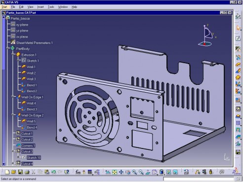
The generative sheetmetal design workbench is a new generation product offering an intuitive and flexible user interface.
The generative sheetmetal design workbench introduces some new and enhanced functionality to the creation of sheet metal parts.
Additionally in the new versions the generative sheet design toolbar is replaced with several toolbars this provides logical grouping of functions for enhanced accessibility.
It provides an associative feature based modeling making it possible to design sheet metal parts in concurrent engineering between the unfolded or folded part representation.
Therefore exceptions can be there for complex features design.
Solid modelling is the parts created with all the features like holes and machining surfaces and few additional manufacturing processes.
But it does not inc.
Following all sheet metal design guidelines is very difficult in the complex part.
Generative sheet metal design overview.
Generative sheet metal parameters overview.
2 answers 1869 views 1 follower what is the difference between merging distance and distance objective in join and healing command catia.
Hello this difference is not only in solidworks but will be there for all the softwares.
Catia difference between part design and surface design.
This helps in delivering the product at low cost and faster timelines.
You can also verify sheet metal features or the entire part against these standards.
Aerospace sheet metal design catia v5.
Although the generative sheet metal design workbench gives us the user an extensive list of tools to choose from it can have some limiting factors.
Sheet metal design guidelines are followed to design quality sheet metal enclosures.


